Theory and Method
QualiCSA™ 5 performs carbon and sulfur analysis using high-frequency induction combustion in oxygen. Combustion converts carbon-bearing species into CO/CO₂ and sulfur into SO₂. The gas stream passes through dust and moisture handling, then carbon monoxide is converted to CO₂ for complete carbon measurement. Infrared cells measure absorption for CO₂ and SO₂, and the software calculates total carbon and sulfur from calibrated curves.
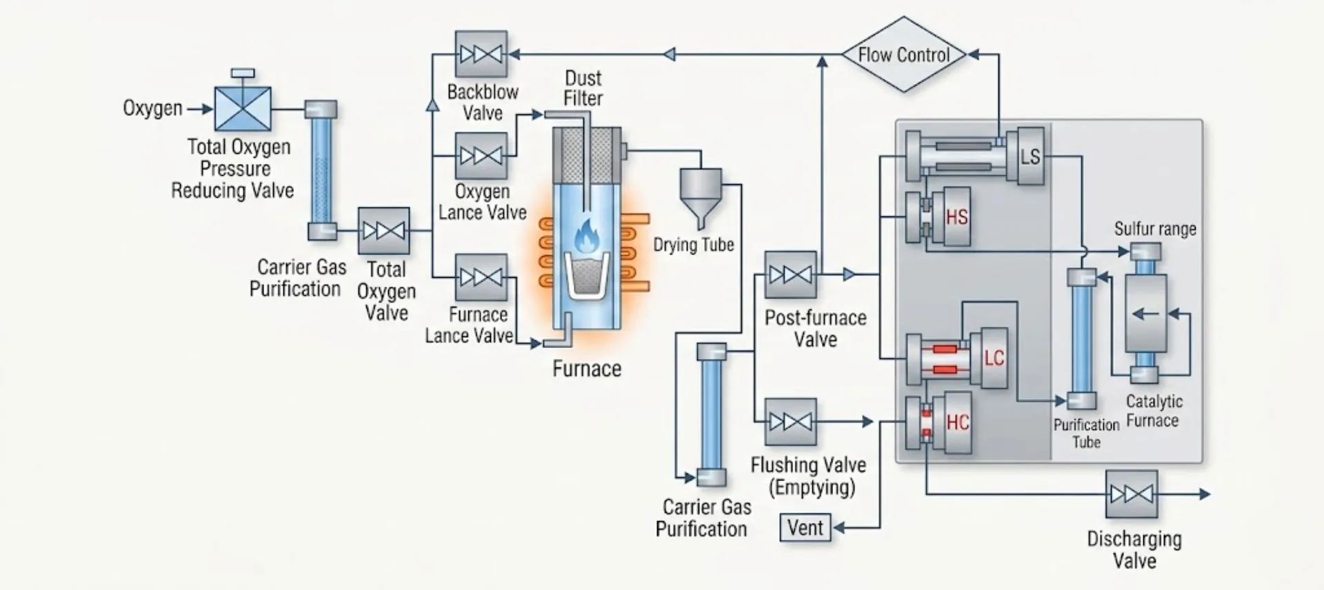
This diagram shows the gas flow path inside the QualiCSA™ 5 carbon and sulfur analyzer during high-frequency combustion and IR detection. It explains how oxygen is controlled, how combustion gas is cleaned and dried, and how the IR cells measure carbon and sulfur signals before exhaust.
Working Principle
1) Oxygen supply and pressure control
- Total Oxygen Pressure Reducing Valve regulates incoming oxygen pressure so flow stays stable.
- Oxygen then passes through Carrier Gas Purification to remove contaminants that can affect low-ppm carbon and sulfur analysis.
- The Total Oxygen Valve acts as the main on/off control for oxygen into the system.
2) Oxygen routing to the furnace
Two controlled oxygen paths feed the combustion zone:
- Oxygen Lance Valve supplies oxygen for combustion support and stable gas transport.
- Furnace Lance Valve directs oxygen into the furnace area to ensure complete burning of the sample.
A Backblow Valve is included to reverse-flow oxygen briefly when needed. This helps clear lines and reduce dust carryover into the gas path.
3) Dust capture and moisture removal
After combustion, hot gas enters:
- Dust Filter to trap combustion ash and particulate debris.
- Drying Tube to remove water vapor so the IR cells don’t drift or saturate during measurement.
This section protects the optical system and improves repeatability between samples.
4) Post-furnace switching and purge functions
- Post-furnace Valve controls whether gas moves into measurement mode.
- Flushing Valve (Emptying) allows the system to purge and reset the gas path between tests.
- A second Carrier Gas Purification stage can further stabilize the gas stream before measurement.
5) Flow control and IR detection cells
The Flow Control block maintains a steady gas flow through the measurement chamber. Stable flow is important because IR absorption depends on a consistent gas volume and path.
Inside the measurement chamber are multiple IR channels:
- LC / HC = low and high carbon channels
- LS / HS = low and high sulfur channels
This design supports wide dynamic range. The analyzer can use the low channels for trace levels and switch to high channels for higher concentrations.
6) Purification, catalytic conversion, and exhaust
Before venting:
- Gas passes through a Purification Tube to protect downstream components.
- A Catalytic Furnace converts gases as needed for accurate carbon reporting and cleaner exhaust handling.
- The Discharging Valve vents the processed gas safely out of the instrument.
Why this all steps matters
- Cleaner gas = better low-ppm stability (purification + dust + drying stages).
- Steady flow = repeatable IR readings (flow control before IR cells).
- Wide range without reconfiguring hardware (low/high carbon and sulfur channels).
- Fast cycle reset (flush/emptying valve and controlled routing).
